Leo's Injectors Circuit Board Writr-Up
Component:
Positive/Negative Input
Channel One and Two Input
Jumper Wire
2x500Ω Resistors
2x1000Ω Resistors
2xLED (Yello)
2xNPN BC547 Small Signal Transistor

Calculations:
Ohms law
Ohm's law:The current flow through a resistance there must be a voltage across that resistance. Ohm's law shows the relationship between the voltage current and resistance.
Kirchhoff's Law
Ohms law
Ohm's law:The current flow through a resistance there must be a voltage across that resistance. Ohm's law shows the relationship between the voltage current and resistance.
Kirchhoff's Law
Kirchhoff's Law: The voltage supplied to a circuit is used within the circuit before it goes back to the power source. .

12-0.8-0.2=10V
R=V/I
R=10/0.02(20mA)=500Ω
Preferred Values of 500Ω for R1,R2
Specs transistor
Ic=100mA
Vce=45V
Vcb=50V
Veb=6V
R=V/I
R=4.4/0.0044=1000Ω
Preferred Values of 1000Ω for R3,R4
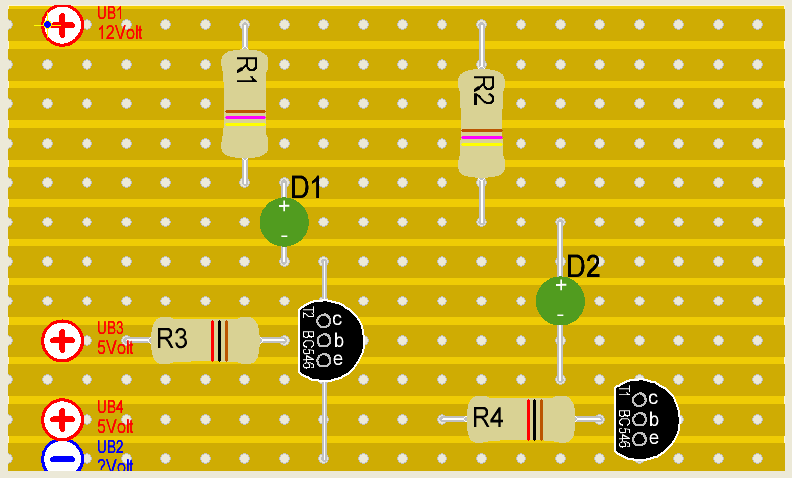
I also build this circuit on lochmaster:

How the circuit works:
Transistor :
The transistors control the electrical current and the amount of current. The transistors have two types N-type and P-type, that depending on which used to dope germanium, the N-type lets electrons flow out of the germanium and the P-type lets the clectrons flow into the germanium. When two semiconductor are placed either in an N-P-N or P-N-P pattern that will be a juction transistor. The juction transistor center layer is the base when electricity is applied to the base, electrons will moving slowly from N to P, the speed will pick up when the more electron change side.
The transistors control the electrical current and the amount of current. The transistors have two types N-type and P-type, that depending on which used to dope germanium, the N-type lets electrons flow out of the germanium and the P-type lets the clectrons flow into the germanium. When two semiconductor are placed either in an N-P-N or P-N-P pattern that will be a juction transistor. The juction transistor center layer is the base when electricity is applied to the base, electrons will moving slowly from N to P, the speed will pick up when the more electron change side.
Voltage supply goees into the positive input and a second supply is needed to be attached to the channel one input. The earths of both supplies are placed up on the negative input. These connections in place the yellow LED will be light and show the channel one is working. The voltage goes into the positive rail 500Ω resistor is placed in series before the LED, the LED connect the resistor and the transistor. At the 5V channel one input rail, there is 1KΩ resistor running into the base leg of the transistor. The emitter is connected by use of a jumper to the negative rail, Channel two works as same.
Test Procedure
Test this circuit we should have 12V Supply and 5V Supply. The negative from both power supplies are to be connected to the negative input. The 12V positive is connected to the positive input. The 5V positive is placed on either the channel one or two input of the circuit based on which channel you want to activate.
Problems:
There is no problem when I made this circuit. I placed in all the components and tested the circuit,it worked good.


Blew is some pictures of my PCB board:


Not enough thoery on any components or what your testing/building. "how the circuit works" paragraph has been a straight copy & paste from (http://regan-chrustowski.blogspot.com/2010/08/injectors-circuit-board-write-up.html)& doesnt even make sense according to what you built.
回复删除Nice stuff!You have presented it very well...pcb Prototype
回复删除